Calypso Capers

Fitting Out Underway…

Fitting Out Underway…

Fitting Out

During our first long term cruise, this year we knew that we had a few creaking systems and lacked some systems that we would want to install to make life on board more comfortable. We mostly managed, but the old fridge (scheduled for replacement at the end of the cruise) lasted only 2 days before being pronounced dead!

We had issues with a lack of sufficient battery capacity, and the engine alternator was not up to supplying our power needs when not hooked up to shore power. The suitcase generator proved handy when moored for long periods in the rivers of Devon and Cornwall, but takes up valuable lazarette locker stowage space and is a bit noisy. The only advantage of the fridge failure was that we didn’t have to fire the generator up very often!

We always knew that we would be upgrading the electrical installation for cruising, but managed (with many compromises) to keep the lights lit throughout the summer without wrecking the 220ah battery bank.

We avoided the very tight marina at Ardglass when traveling down the Irish coast, resulting in a 16 hour passage from Belfast to Dublin, which would have been nicely broken up had we stopped over at Arglass – but we weren’t going in there without a bowthruster (Calypso steers well going ahead, but is very difficult to maneuver in astern). We read the blog of one couple who had to reverse out of a tight space and all the way out of Ardglass marina as there was no room to turn. And so Paul’s retirement present from Val was to be a bowthruster!

We also wanted to upgrade our electronic navigation system and install a holding tank.

Over the last 3 years (since acquiring Calypso) we had researched various aspects of our fit-out proposals, including who we wanted to do the work. We settled on Osmotech at Hamble Point marina for much of the work – better to have one contractor dealing with various aspects than a number of different contractors – with the likelihood of each getting in the others’ way and all blaming each other for problems arising.

Osmotech would deal with the bowthruster (they install hundreds), electrical upgrade and holding tank. Hudson Marine Electronics (based in nearby Mercury marina) would supply and install the new chartplotter and radar (they often work with Osmotech so there was less likelihood of them treading on each other’s toes). We had strong local recommendations to use Ted French at Abbey Engineering for stainless steel work (and he has also worked with Osmotec from time to time).

Finally, we wanted to improve engine efficiency and reliability and to change the saildrive seal. Wayne Pickersgill of Marine Drive Engineering was highly recommended – and now we know why!

[ EDIT – As we speak now, with the fit out completed, we are happy with our choices.]

So here is a resume of the fit-out works:

BOWTHRUSTER

On the bowthruster front – we now have a Sleipner Sidepower thruster fitted with joystick at the helm and a remote which operates both thruster and windlass. We had envisaged that the thruster would have its own battery that would then be shared by the windlass, but the advice was to keep it separate.

The thruster tunnel, motor and battery have taken up a majority of the space under the forward bunk, although we have now installed a panel to separate the useful remaining space. Given the addition of the new (and heavier) 25kg Rocna anchor and longer (85m) anchor chain plus the weight of the thruster, we will ensure that only lightweight bulky items are stored within this area.

ELECTRICAL UPGRADE

Three new Rolls AGM house batteries are installed, totalling 345ah. Ideally we would have liked more capacity but that would have required creative fibreglass work in their installation. The Rolls units just fit into the existing battery box moulding. We have undertaken a power audit and feel we can live with this, provided that the new fridge system will work as envisaged (see below). We have moved the engine battery into the engine compartment to make way – not ideal (temperature wise) but we’ll see how that goes. New engine and thruster batteries are Optima Blue Top, AGM style batteries which simplifies the charging regime (we assume that this is better than having different battery technologies given that all are linked in the charging system).

The old Victron Centaur mains charger has been sold and replaced with a Victron Multiplus 12v/3,000w/120a. The charging capacity is greater than needed (but is set to charge at 60amps) but this was an “eBay bargain”, and the 3,000w inverter, set to operate as an uninterrupted power supply through the boat’s existing 240v ring main, will be very useful.

The charger/inverter sits within the forward storage compartment beneath the aft port cabin (“the garage”). Osmotech installed a very attractive vent with polished timber frame that looks like a factory fit, but it was important to introduce ventilation within this locker to avoid overheating.

The main charger channel feeds the house batteries, with the second 4amp channel set to charge the engine battery. The smart multi-stage charger has a battery temperature probe to prevent overheating. Ventilation gaps around the Rolls batteries is less than ideal. 

A control panel for the multiplus is fitted at the nav station which allows a choice of Off/On, Charger/Inverter and shows charging stage

Osmotech suggested installing a battery paralleling switch to enable us to use the house batteries to start the engine in an emergency, and that seemed like a good idea to us.

The new solar panel set up comprises 3x 80w Victron rigid panels mounted on the new rear arch. These are wired in parallel and charge the house batteries via a Victron MPPT regulator (with a smart dongle blue-toothing power generation data to an app. on the iPhone that we can bore visitors with!) A VSR will sit between house and engine battery and another will sit between engine and thruster batteries.

At anchor we will be able to deploy two further solar panels totalling 107w, each with its own solar regulator, and the total solar array should more than satisfy our needs at anchor. We have considered and (for now) dismissed wind generation – firstly because we understand that there are too many windless days in the Mediterranean; secondly, affixing a wind generator above the solar arch will cause shading of solar panels (and a very small percentage of a panel in shade will cause a very disproportionately high reduction in power generation). Our cruises will be limited to summer months, but we would probably have to add wind power if cruising off-grid very early and late season.

This set-up is unlikely to satisfy all of our power requirements, even though we have introduced measures to make our system function well: replacing all internal and navigation lights with LED units, adding insulation to the cool box and selecting a refrigeration system to best suit our off-grid power generation method (solar) – see below; our new Quantum radar is far more energy efficient than the old one. However on longer passages, particularly overnight (or on cloudy days) we will have an energy shortfall when running autopilot, lights and nav. instruments/radar without running the engine.

It was apparent during our cruise this year that our original fit alternator was not up to generating sufficient power to allow autopilot use on longer passages. On occasions we turned everything off and sailed by the compass, including 25+ hours handsteering from Milford Haven to Falmouth!

Many older alternators are not set up to deliver high output at low engine revs, and generally their output (without a smart regulator) is at relatively low voltage for optimal battery charging.

We have therefore invested in a Balmar alternator with smart regulator. We were debating the merits of a 110amp unit versus the next size down at 70amps (Barden having recommended 90-100amps). The 110amp unit would certainly generate sufficient power – especially considering that the Balmar units apparently generate much higher output at the low revs associated with marine diesel engines compared with many standard automotive alternators – however there would be concerns over belt wear and breakage in use at full power (the Balmars can be turned down to half power at the flick of a switch when high power generation is not required).

Our overnight passages will be few and far between. We did not want to specify a battery bank capacity based upon an overnight passage, and so will use engine alternator power generation when required overnight. It may be that 110amps would be needed to replenish batteries whilst sailing on autopilot overnight without having to run the engine for longer than we would find acceptable, but we have not really got our limited knowledge around that one!

Our longest passage is likely to be 3 days across Biscay. If need be we can turn the fridge off for that period to conserve energy.

Will that work with a 70amp Balmar? We don’t know.

The cost of the 110amp Balmar plus regulator is £1,000. We could add a serpentine belt kit at a further £500 or so to overcome belt wear problems, but do we actually need 110amps?

Our deliberations were interrupted when a 1 year old 70amp Balmar and regulator came up on eBay, which we snapped up for £225 including postage (the owner re-engined and the unit was not compatible with the new engine).

The Balmar regulator is linked to the engine battery, but will charge the house and thruster banks as the VSR activates when the engine battery voltage reaches full charge.

We hope that this set-up, combined with the intended refrigeration system, power conservation measures on overnight passages and our ability to be energy frugal when needed will enable us to manage with the 345ah house battery bank. If not we should have no difficulty getting our money back on the Balmar and will have to spend more of the kids’ inheritance to upgrade. Watch this space!

To monitor battery state we will use a Merlin Smartguage. This unit is something of a mystery – experts do not seem to know how it works, but independent tests have shown it to be the most accurate unit for indicating the state of the batteries by percentage charge.

When we first came across this a few years ago it was being marketed on a low key basis by its inventor. In spite of the doubts expressed by many, the design was acquired by Merlin, and is also sold in the USA under the Balmar badge. If those two companies have confidence in the unit then that is good enough for us!

REFRIGERATION

The fridge will represent a significant proportion of our energy consumption, especially as we head south into warmer climes. We have, therefore, removed the original fit air-cooled refrigeration unit have replaced it with a eutectic tank system by Ozefridge, imported from Australia.

The eutectic tank sits in the refrigerator and contains an ethylene glycol solution, mixed to achieve a freeze point of minus 6c.

The controls allow you to set a tank temperature at which the compressor cuts off, recommended at minus 10c.

When the solar panels are generating power, or when the engine is running, the fridge’s control system detects surplus energy generation and uses it to keep the tank nearer to the low point set (-10c).

When the sun goes down and the engine is off then the control system senses this and allows the temperature in the tank to sit a little higher, so less power is drawn overnight.

As the ethylene glycol defrosts it generates active cooling by the energy released during the change of state (solid to liquid) as the “latent heat of fusion”, without any drain on the battery bank during the periods when no energy is being generated. Paul quickly understood the concept and would like to thank Rocky Ramsgill (bless his soul) for his patience in O level physics lessons!!

To illustrate the concept – when to cool a given quantity of water by 1*c takes 1 unit of energy, to cool that same quantity by 1*c when the water freezes will take 80 units of energy. You can switch the system off overnight, when that energy is released and actively cools as the ice melts – so in effect this acts as an additional energy store (battery). Cool – I have bored the pants of many people with this revelation already. Hopefully I will stop soon!

The system uses water cooling (when coolant level sits above a certain temperature) and a 20 litre tank (a modified caravan holding tank at £30 including brass nipples for water supply/return) is installed in the bilges for this purpose. The system is still not quite as energy efficient as some modern water cooled compressor systems (according to the refrigeration engineer who degassed the old system for removal). However by using more energy at the time of generation this should reduce the need for overall energy storage (battery) capacity. Note that the system also has air cooling in the event of interrupted cooling water supply, but in that mode is less efficient in a hot climate.

Our research suggests that this system is also much cheaper than going down the keel cooler route. The cost, including import duties, was somewhere in the region of £15-1700 from memory – more than it would have been when we researched the system with the Aus dollar at 2 to the £!

Additionally we have also beefed up the external insulation around the fridge. When our fridge packed up early this year we packed polystyrene around it and were pleasantly surprised at how much longer a 2kg pack of ice cubes lasted! The polystyrene has now been replaced with the less flammable building product, Celotex.

The system uses water cooling (when coolant level sits above a certain temperature) and a 20 litre tank (a modified caravan holding tank at £30 including brass nipples for water supply/return) is installed in the bilges for this purpose.

The system is still not quite as energy efficient as some modern water cooled compressor systems (according to the refrigeration engineer who degassed the old system for removal). However by using more energy at the time of generation this should reduce the need for overall energy storage (battery) capacity. Note that the system also has air cooling in the event of interrupted cooling water supply, but in that mode is less efficient in a hot climate.

The eutectic tank fits nicely in the coolbox, although some glassfibre repairs are required:

So far the system seems to be working extremely well, and runs very infrequently – however we have not yet seen air temperatures above 17*c.

There is a little fine tuning to be done once the system is installed: we had to release refrigeration gas, a little at a time, until one of the pipes leading from the compressor stopped icing (externally). We adjusted the ethylene glycol dilution rate (simply removing some of the solution and adding more water) until we got the freeze point to minus 6*c as recommended, but the DIY fit really was very easy, and the fridge now seems bigger and easier to organise.

Paul had to contort his body to reach into the far corners:

The Ozefridge system is a DIY fit, comes ready gassed and simply requires the addition of antifreeze poured into the eutectic tank. See here for the website of Ozefridge, who have estimated that the new system, with the additional insulation, will use no more than 23ah daily in Mediterranean temperatures. It is also engineered so that the phased start up period takes no more current than the running current.

Whilst we have read forum reports that would support the daily power usage claim, we have assumed a little more in our energy audit, however for us the most important factor in selecting this system is the reduced need to increase our battery capacity to cope with overnight power consumption.

As anticipated, the compressor and control system fitted into the space with not a millimetre to spare (height wise):


STERN ARCH

We cannot argue against the opinion of many that a stern arch is detrimental to aesthetics! However we are prepared to accept that disadvantage to enable us to permanently mount an array of solar panels, needed to support our 6 month live-aboard needs. Nonetheless we have sacrificed some of the potentially available transom width in favour of aesthetics.

At some point over the next 2 years (before we hit Southern Portugal) we will have a bimini cover installed above the cockpit. We have seen semi-permanent biminis carrying semi-flexible solar panels zipped to the bimini cloth, however we wish to be able to easily fold back the bimini, which will be deployed only when necessary. On this basis (and with other functions in mind) we took the decision to construct a stainless steel arch across the stern.

We calculated that we could comfortably accommodate 300 watts or so of rigid solar panels on the rear arch using the full width of the stern, but in a compromise between function and aesthetics we have arrived at an arch design that will carry 240watts, with the area occupied by the panels at around 2.6 x 0.6m. Further panels will be temporarily deployed at anchor as described above.

The design we arrived at was one that will:

  • be integral to the front pushpit stanchions (to avoid overcrowding of stainless work around fairleads/cleats/winches);
  • strengthen the rear section of the pushpit with a new stanchion from transom to pushpit to solar platform – this has allowed us to mount the liferaft on the rear pushpit rail, which was previously not strong enough (and the alternative side mounting location puts the liferaft in the way of fairlead and cleat on the stern);
  • be swept back to improve aesthetics and to enable us to stand on the rear helm seat without having to make the arch excessively high;
  • Sweep inwards from the front pushpit stanchion so that the width of the solar platform is somewhat narrower than the stern of the boat – to improve aesthetics;
  • not overhang the rear of the boat (which would add to berthing costs which are based on overall length!);
  • have two attachment hoops welded on the inboard section of the solar platform which will allow us to hoist the dinghy vertically across the transom with hoisting blocks;
  • have one attachment hoop welded on one side of the outboard section of the solar platform to be used for an outboard engine hoist (and we have sold the Plastimo stainless engine hoist that we fitted last summer!);
  • have a plate fitted to attach the stern light which is best placed well above the waterline;
  • allow cables to run internally, within the 38mm stainless tube and directly through that into the transom void.
  • have sidebars midway between the upper pushpit rail and the solar platform where aerials can be mounted without overshadowing the solar panels. No doubt other general gubbins will become attached here!

We had considered the benefits of introducing mounts to enable us to tilt panels towards a setting sun. However the concensus on forums was that this delivers little benefit compared to additional cost and daily effort – and when at anchor we can point the roving panels at the sun if we need to/can be bothered. The tilting mechanisms that we have seen are not pretty and add more things to go wrong, so we are keeping the design simple.

So – a lot of thought has gone into this. Our fabricator, Ted French at Abbey Engineering, listened to our thoughts very carefully, drew up sketch plans and visited the boat on three occasions before starting fabrication – and on the last occasion brought a mock-up of the section of the arch stanchions to ensure that we were happy with the appearance and function of the design before making a start on fabrication. Ted is highly regarded by two of the contractors we have been using and we are delighted with the result.

HOLDING TANK

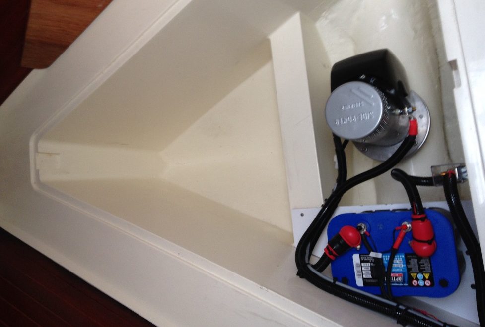
We expect that we will spend more nights at anchor off beaches in future. We will have no access to marina facilities but would not want to flush the toilet overboard in that situation. The installation of a holding tank is, therefore, important to us.The aft port cabin is now used only as our “garage” and as we wanted to install a gravity emptying system we can happily sacrifice the hanging locker in there to accommodate the holding tank.

We needed to maximise the size of tank without undertaking major joinery surgery: a limitation on size was the door leading into the cabin which is quite narrow. However removing an emergency escape kick-through panel between port and starboard cabins allowed us to make the tank 25mm wider – as the starboard cabin door and kick-through panel are both wider than the port cabin door.

The capacity of 89 litres is sufficient for two of us to spend several nights without having to lift anchor. Just in case we want to stay longer we have replenished the supply of a product that we used last year. We will not go into that here, but those interested can Google “Disposa-John”.

Tek Tanks will no doubt retain the tank design within their archive – But S38 owners wanting to use this design should check their access route (we have no idea if the kick-through panel is a standard uniform size in all S38s). Any S38 owners with a single aft cabin will have to check whether the same hanging locker was installed, and if so will need to carefully consider whether the waste outlet can be routed without entering the cabin space – in our 2 aft cabin version the bunk locker abuts the hanging locker.

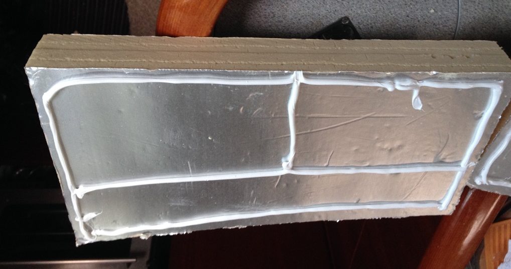
Tek Tanks fabricated the new tank using a plywood mock up created and tested for fit by Osmotech. There is an existing design for the Moody S38 which sits within the bilge below the companionway steps. However this is below the water line and relies on active pumping to empty the tank.

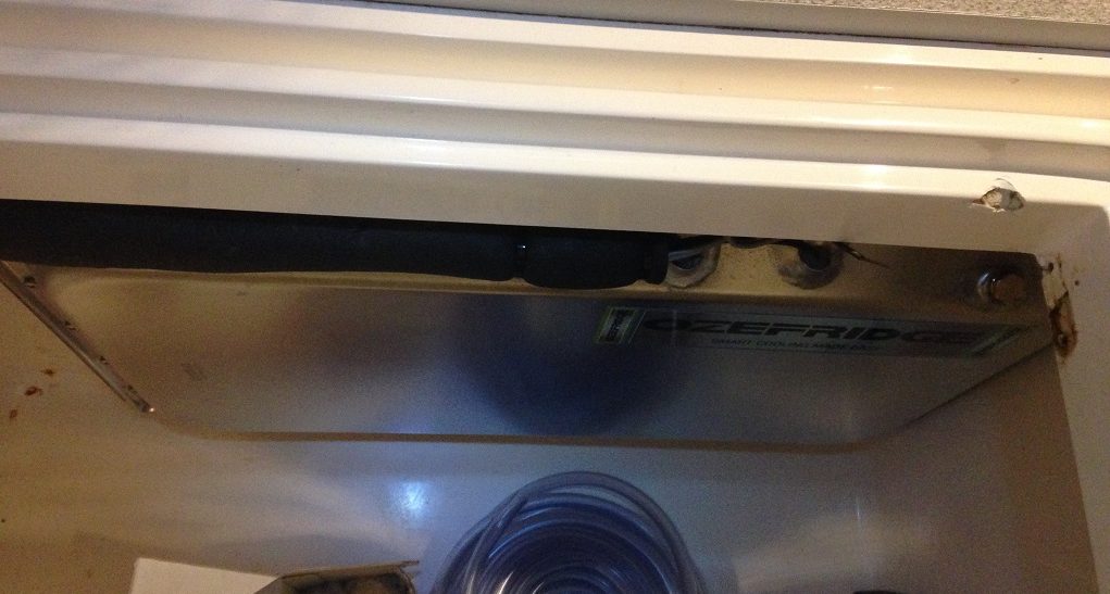
Our design sits above the water line and is a gravity discharge system with alternative deck pump-out. The deck pump-out sits directly above the gravity overboard discharge outlet in the bottom of the tank, meaning that if we are very careless and have a blockage we will be able to rod the outlet from the deck pump-out neck. The over-sized 2″ waste pipe outlet was installed with the gentlest curve possible (and 2 x 45 degree angles on the through hull tail) to help prevent blockage and also facilitate rodding. A new waste through-hull was installed in the front locker beneath the port cabin bunk. The tank is closed off and opened (emptied) with a simple 2” seacock at the through hull position. The 2″ waste pipe was surprisingly difficult to source.

For us, using the port aft cabin as a garage, losing the hanging locker is a good compromise to enable us to install a gravity discharge system with easy rodding capability. For others that may not be the case.

Our design includes a (larger than standard) 2” outlet pipe (minimising blockages) and a 1.5” air vent (a narrow vent would risk implosion of the tank when waste is pumped out). We are not installing a charcoal filter on the air vent – the tank should not smell noticeably if properly used, and the stories of charcoal filters being accidentally filled with effluent put us off that idea! We purchased a Gobius tank level indicator system at the Boat Show – this uses external sounding sensors and so there are no moving parts inside the tank (not yet fitted on the photo below).

We are retaining the original through hull/seacock outlet and a Y valve within the heads will enable us to select flushing to tank or directly overboard.

RADAR, PLOTTER AND AIS

We decided to replace the Raymarine C80 plotter – and because the analogue radar is incompatible with new generation plotters we would have to replace that, but could retain the ST60+ instruments. We elected for a Raymarine e95 hybrid touchscreen plotter and the new technology Quantum radar.

The new plotter is mounted in a pod under the sprayhood. This is viewable from the helm (with good eyesight), but has the advantage that all crew in the cockpit can see it (important when the navigator is not helming) and the autopilot can be controlled from under the sprayhood in adverse weather.

The new plotter will also connect to the iPad below decks, and with the app installed can be controlled from the iPad. This will allow the resting navigator to check on progress from a bunk!

The new Quantum radar is new technology – see here for a PBO review. The major deciding factor for us was the reduced energy requirement – 17w against 40w for a comparable digital unit (7w as against 20w on standby). The new Quantum uses Bluetooth/wireless signals to the plotter and is half the weight, so whilst we did not intend to replace the radar when getting the new plotter, we are not unhappy that we had to do so because of compatibility, and will benefit from the improved clarity of this new technology.

RADAR, PLOTTER AND AIS

We decided to replace the Raymarine C80 plotter – and because the analogue radar is incompatible with new generation plotters we would have to replace that, but could retain the ST60+ instruments. We elected for a Raymarine e95 hybrid touchscreen plotter and the new technology Quantum radar.

The new plotter is mounted in a pod under the sprayhood. This is viewable from the helm (with good eyesight), but has the advantage that all crew in the cockpit can see it (important when the navigator is not helming) and the autopilot can be controlled from under the sprayhood in adverse weather.

The new plotter will also connect to the iPad below decks, and with the app installed can be controlled from the iPad. This will allow the resting navigator to check on progress from a bunk!

ENGINE WORK

Before setting off we wanted to undertake some preventative maintenance in the engine compartment, and Wayne of Marine Drive engineering came aboard to replace the saildrive seal, look at the exhaust elbow and change the diesel injectors. CONTINUED…

One Response

  1. Hope the installation process is progressing well as the 3 day journey across Biscay will be demanding I am sure. In the ferry ,a few years ago , it took 38 hours,should have been 33 but due to weather conditions it took longer as the usual course had to be differed.
    Hope for more detail before your 2017 trip begins. X X

Leave a Reply

Your email address will not be published. Required fields are marked *

This site uses Akismet to reduce spam. Learn how your comment data is processed.